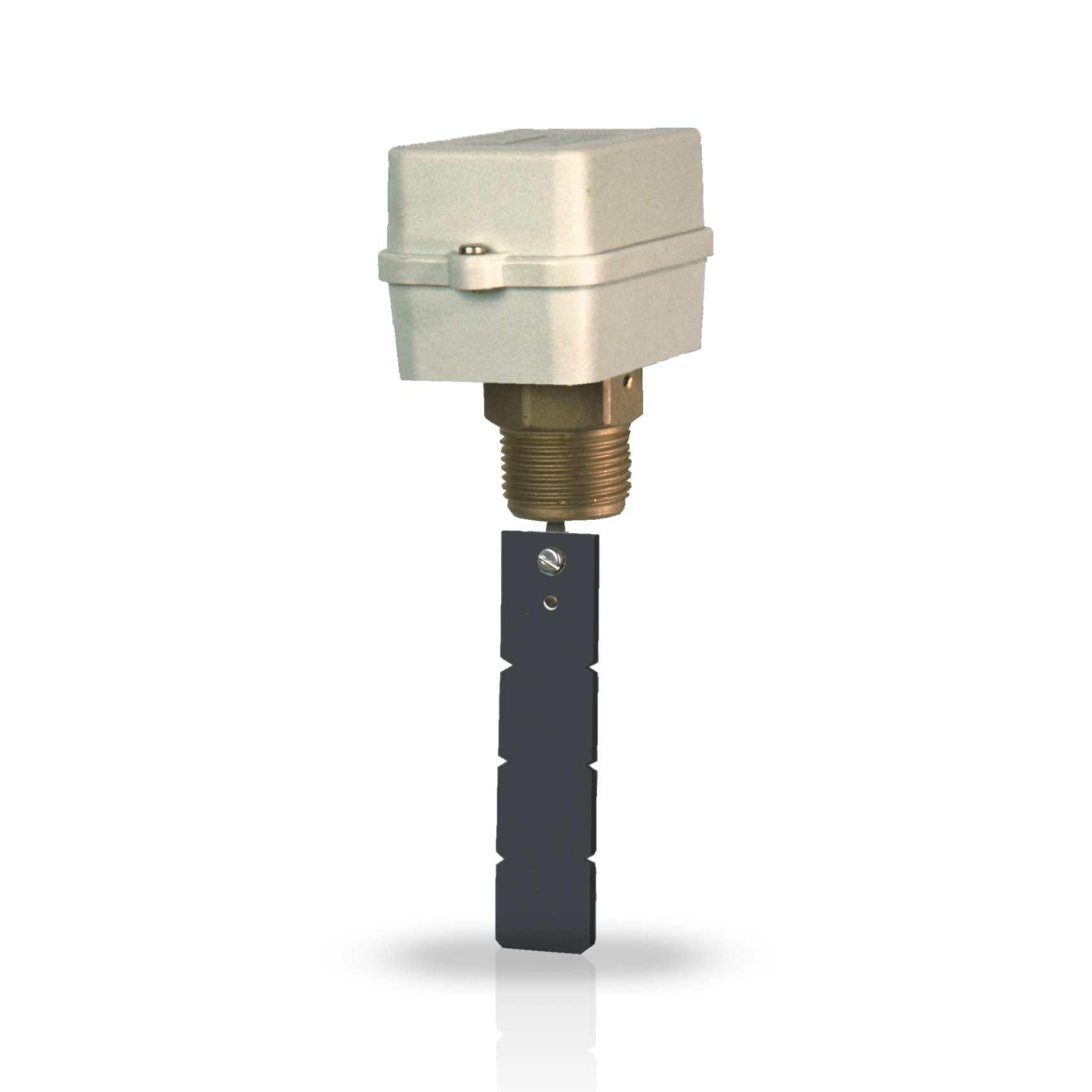
Liquid flow switch with plastic paddle and casing

-
DESCRIPTION
General features0
Flow switches are used to signal, control, and regulate the flow in a pipe. They are commonly applied for pump control, burner activation, compressor management, alarm signaling, and motorized valve operation.
Type FF81P
- Shock-proof thermoplastic case with self-retaining screws.
- Threaded brass connection: G1.
- Nylon cable gland: G 3/8.
- Non-toxic thermoplastic resin paddle: Starting from G4, with cutting references for G1, G2, G3.
- Electrical connections: Faston 6.3 (included).
- Adjustment screw for setting the intervention point.
- Unit weight: 0.36 kg.
Type FF91P:
- Shock-proof thermoplastic case with self-retaining screws.
- Threaded brass connection: G ½.
- Nylon cable gland: G 3/8.
- Non-toxic thermoplastic resin paddle: Starting from G2, with cutting references for G 1/2, G1, G 1+1/2, G2.
- Electrical connections: Faston 6.3 (included).
- Adjustment screw for setting the intervention point.
- Unit weight: 0.25 kg.
Electric features- Rated insulation voltage Ui 380V~
- Continuous duty rated current Ith 10A
-
ADVANTAGES
0
Flow switches are used to signal, control, and regulate the flow in a pipe. They are commonly applied for pump control, burner activation, compressor management, alarm signaling, and motorized valve operation.
Advantages -
TECHNICAL SPECIFICATION
* For drinking water control, a maximum of 85°C is recommended.
CODE PIPE DIAMETER MINIMUM CALIBRATION VALUE (dm³/sec) WITH FLOW INCREASING MINIMUM CALIBRATION VALUE (dm³/sec) WITH FLOW DECREASING MAXIMUM CALIBRATION VALUE (dm³/sec) WITH FLOW INCREASING MAXIMUM CALIBRATION VALUE (dm³/sec) WITH FLOW DECREASING MALE CONNECTION MAXIMUM PRESSURE OPERATING OPERATING TEMPERATURE * PROTECTION DEGREE UNIT WEIGHT KG FF81P G 1 0.26 0.16 0.58 0.53 G1 10 bar 0 ÷ 100 °C IP54 0.36 G 2 0.87 0.65 1.65 1.74 G1 10 bar 0 ÷ 100 °C IP54 0.36 G 3 1.85 1.3 3.49 3.27 G1 10 bar 0 ÷ 100 °C IP54 0.36 G 4 2.39 1.85 5.56 5.23 G1 10 bar 0 ÷ 100 °C IP54 0.36 FF91P G 1/2 0.13 0.08 0.29 0.26 G1/2 10 bar 0 ÷ 100 °C IP54 0.25 G 1 0.26 0.16 0.58 0.53 G1/2 10 bar 0 ÷ 100 °C IP54 0.25 G 1 1/2 0.39 0.24 0.87 0.79 G1/2 10 bar 0 ÷ 100 °C IP54 0.25 G 2 0.8 0.6 1.7 1.6 G1/2 10 bar 0 ÷ 100 °C IP54 0.25 -
HOMOLOGATION AND INSTALLATION
Homologation
- Complies with CEI EN 60947-5-1 standards
Installation and useThe flow switch must be installed on horizontal pipe sections, positioned away from valves, elbows, drains, or any areas with irregular flow patterns.
A flexible paddle, activated by the flow of liquid, engages the operating lever of a SPDT switching microswitch, triggering the following actions:
When the flow increases: the C-NC contact opens and the C-NO contact closes.
When the flow decreases: the C-NC contact closes and the C-NO contact opens. - TECHNICAL LITERATURE
-
FAQS